Journal Information

Article Information


Original Paper

Heat Generation and Defect Analysis of Welding Process using Thermography System

Yong Jin Cho[*], Yeong Do Park[*][]

Abstract

A thermography system collects the radiant energy emitted from the target by a detector, converts it into an electrical signal, computes the quantitative physical value through the input algorithm, and visualizes the heat distribution on the surface of the target. Thermography systems, which are representative of non-contact measuring instruments, have been steadily expanding in various fields such as military, medical, electrical, and machine defects owing to the development and popularization of infrared technology. Herein, the heat generation and defect analysis of projection welding and the cold metal transfer (CMT) welding process were performed using a thermography system. The factors considered in the projection welding and the CMT welding process are the chemical constituting the material and the amount of energy input to the unit length. From the study, we present the results of the fracture strength of the welded material and the heat distributing on the surface of the material during the two welding processes. Through this study, we confirmed that the heat distribution and physical properties of the material surface, as obtained by a thermal imaging system, are critical to ensure the quality, strength, and stability of welding.

Keywords: Cold Metal Transfer welding, Nut Projection Welding, Radiant Energy, Thermography System.


1. Introduction

A thermography system collects the radiant energy emitted from an object, using a detector in a non-contact manner, calculates the quantitative physical properties, and visualizes the heat distribution on the surface of the object through thermal imaging. In recent times, owing to the rapid development and popularization of infrared technology, the use of a thermography system has been consistently expanding in various areas, including military, medical, electrical, and machine defects [1,2].

Welding is a technology to induce a direct bond between solids by applying heat and pressure to two or more metal materials, and is generally used in steel industries, such as aviation, ship-building, and automotive.

Hitherto, various welding types have been introduced. Among them, nut projection welding, a kind of resistance welding, combines materials by providing projections to the nut to be joined, applying pressure, and generating resistance heat. Cold metal transfer (CMT) welding increases the surface tension of the weld by allowing the metal transfer of the welding rod to be performed at a relatively low temperature, and produces little spatter by maintaining a stable arc even at a low current.

After welding, the strength and stability of the metal material weld junction are significantly affected by the internal defect of the molten pool that varies depending on the heat energy applied to the weld junction and the chemical compositions of the materials. As for the defect of nut projection welding, researchers have investigated the influence of the nut material on the welding strength and fracture model change [3]. As for CMT welding, a study on the tensile strength and bead shape characteristics according to the welding process parameters using a thin-walled aluminum alloy has been reported [4].

As the temperature of the weld junction typically reaches approximately more than 1,000 °C during welding, temperature measurement by a contact method is impossible. Therefore, in this study, the heat generated during welding was quantitatively measured using a thermography system, which is a representative non-contact measuring instrument, and the defect of the weld junction was analyzed.

As for the welding methods, nut projection welding and CMT welding were selected to investigate the influence of the factors considered for welding on the strength and stability of the weld junction. For nut projection welding, coated and uncoated materials were used to compare the impacts of the chemical factors of the materials. For CMT welding, the amount of energy input to the unit length was adjusted.

From the experiment, we obtained the maximum temperature, energy distribution, and fracture strength depending on the coating for nut projection welding. Further, the defects, such as pores in the molten pool, as well as the tensile strength according to the input energy were presented for CMT welding.
2. Experimental Method

2.1. Thermography system

The thermography system used in this study was FLIR’s A655sc model, which can detect the energy in the long-wave infrared band and control the radiation amount collected through the detector by adjusting the aperture.

Table 1 summarizes the performance of the A655sc model. The thermography system can set the area of interest by adjusting the resolution, and the number of images measured for one second varies depending on the resolution.

Specifications of thermograph system

Optical data of A655sc
IR resolution
  • 640 * 480 pixels at 50 Hz

  • 640 * 240 pixels at 100 Hz

  • 640 * 120 pixels at 200 Hz

Thermal sensitivity/NETD < 0.03℃ @ +30℃/30 mK
Minimum focus distance 0.25 m (25 cm)
Field of vied(FOV) 25˚ * 19˚(31˚ diagonal)
Detector type Focal Plane Array(FPA), uncooled microbolometer
Spectral range 7.5 − 14 μm
Object temperature range
  • −40℃ to 150℃

  • 100℃ to 650℃

  • 300℃ to 2000℃ (Option)

Accuracy
  • ±2℃(100℃↓) or

  • ±2%(100℃↑)

As the heat energy concentrated on the surface of the material during welding occurs in a limited area and the materials are combined within a short period of time, the resolution of the thermography system was lowered and the number of images to be collected was increased in this study.

Sparks from the welding process may damage the lens of the thermography system. Therefore, the distance between the object to be welded and the system was maintained at an appropriate level, i.e., longer than the minimum focal length. In addition, as the temperature at the weld junction may reach more than 1,000 °C, the performance of the thermography system was enhanced such that temperatures up to 2,000 °C can be quantitatively measured.

2.2. Nut projection welding

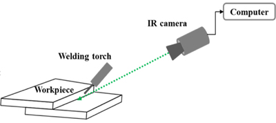
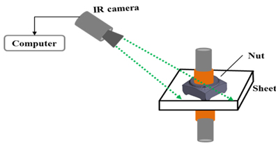
Unlike the typical resistance welding, nut projection welding requires the nugget diameter to be maximized to increase the strength of the weld junction. The nugget diameter varies depending on the current, pressing force, welding time, and chemical composition of the material. Fig. 1 shows the configuration of the nut projection welding used in this study.

Fig. 1

Configuration of nut projection welding

The sheet used in the nut projection welding was a non-plated aluminum silicon (Al-Si) plate with a thickness of 1.2 mm and a hot plate stamped steel plate (steel plate Aluminized Boron Cold rolled) The hexagonal nuts were used. The welder uses a MFDC (Medium Frequency Direct Current) welding power source, and the distance between the thermal imaging system and the welding object in the nut projection welding is set at about 1 m. Table 2 shows the set values of experimental conditions for projection welding.

experiment conditions of nut projection welding

Type Inverter DC (MFDC)
Force (kgf) 500
Current (kA) 17
Weld time (ms) 117

2.3 CMT welding

CMT welding used the short-circuit droplet transfer method, which creates a droplet using the short-circuited welding wire without an electromagnetic force [5]. Among the gas metal arc welding methods, CMT welding provides the benefit of using a lower current and heat input for the same amount of deposition [6]. The application of CMT to the coated material, however, forms pores inside the molten metal, causing CMT welding to be the focus of studies even today. To prevent pore defects inside the molten pool, it is necessary to clearly analyze the formation and growth of pores according to the heat input, coagulation time, and maximum temperature during welding. Fig. 2 shows the configuration of the CMT welding used in this study.

Fig. 2

Configuration of CMT welding

The equipment used for the CMT welding was the MH6/DX100 model, which uses a fully automated gas metal arc welding method. The material used for the CMT welding was the galvanized steel plate with a tensile strength of 440 MPa and a thickness of 2.3 mm. The ER70S-3 with a diameter of 1.2 mm was used as the welding wire. The heat input of the CMT welding varies depending on the voltage, power, and speed of the equipment, as shown in Eq. (1):

where Q is the heat input, V is the voltage, I is the current, and v is the speed. Table 3 summarizes the input information for the CMT welding in this study.

experiment conditions of CMT welding

Voltage (V) 0.014 0.016 0.018
Current (A) 150 190 220
Travel speed (m/s) 0.01 0.01 0.01
Heat Input (J/mm) 209 309 400

3. Experimental Results

3.1 Nut projection welding

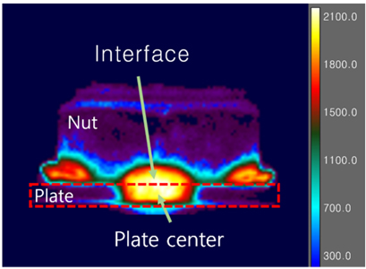
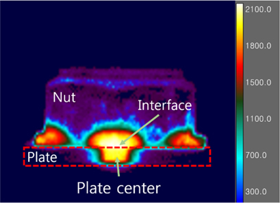
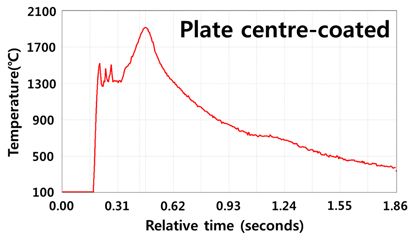
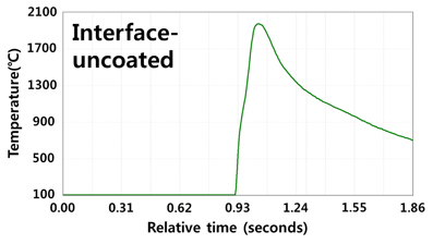
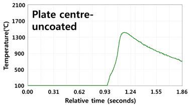
Figs. 3 and 4 show the surface heat energy distribution results of the nut projection welding for the coated and uncoated materials, measured through the thermography system. To distinguish the heat energy distribution of the weld junction, the plate area and the interface area between the plate and the nut were divided, and the quantitative physical properties were extracted [7].

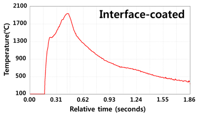
A qualitative comparison between Figs. 3 and 4 reveals that the heat energy distribution of the plate area was similar to that of the interface area when the coated plate was used. Meanwhile, when the uncoated material was used, the plate area exhibited a lower heat energy distribution than the interface area. Figs. 5 and 6 present the quantitative temperature values that occurred in the interface and plate areas of the coated metal.

Fig. 3

Heat distribution in coated steel

Fig. 4

Heat distribution in un-coated steel

As shown in Figs. 5 and 6, the plate and interface areas exhibited the same maximum temperatures. Figs. 7 and 8 show the temperature values that occurred in the interface and plate areas of the uncoated material.

Fig. 5

Measured temperature in coated interface

Fig. 6

Measured temperature in coated plate center

Fig. 7

Measured temperature in un-coated interface

Fig. 8

Measured temperature in un-coated plate center

For nut projection welding, the same nuts were used to examine the impact according to the chemical composition of the plate. The result shows that the maximum temperature at the interface is the same regardless of the coating of the plate. However, the temperature of the uncoated material is lower than that of the coated material. Furthermore, the uncoated material did not exhibit a singularity interval during the course of reaching the maximum temperature because of a low thermal conductivity.

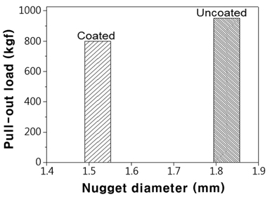
Fig. 9 shows the nugget diameter and tensile strength results of nut projection welding for the coated and uncoated materials. From the results, we confirmed that using the uncoated material resulted in a larger nugget diameter and a higher tensile strength.

Fig. 9

Nugget diameter and pull-out load

3.2 CMT welding

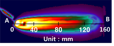
Fig. 10 shows the heat energy distribution during CMT welding. For the CMT welding, the heat energy input to the unit length was adjusted while the movement path and distance were the same.

Fig. 10

Heat distribution during CMT welding

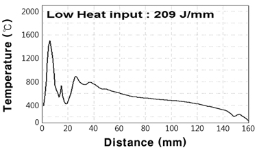
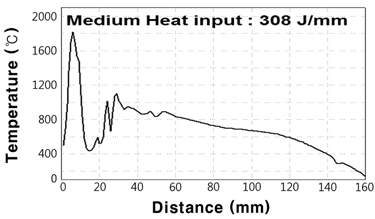
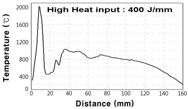
The temperature values for each position measured through the thermography system are shown in Figs. 11, 12, and 13. The maximum temperature was measured at the junction of the welding rod and the plate, and high temperatures were maintained at positions where welding was completed by the residual energy. In addition, as the heat energy input to the unit length increased, the maximum temperature and the residual temperatures at each position also increased.

Fig. 11

Measured temperature following distance in low heat input

Fig. 12

Measured temperature following distance in medium heat input

Fig. 13

Measured temperature following distance in high heat input

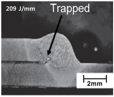
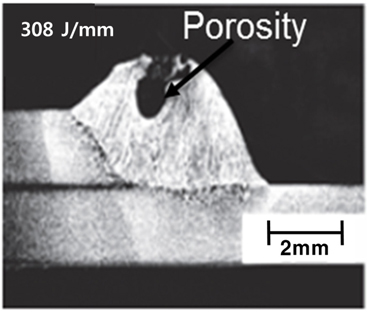
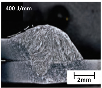
To examine the pore shapes inside the molten pool according to the changes in the heat energy input to the unit length, the welded specimens were cut, and the internal shapes were magnified, as shown in Fig. 14, 15, and 16.

The result of Fig. 14, where the energy input was the lowest, shows that a small pore was formed at the interface between the plates. The pore did not have sufficient time to escape the welding pool owing to the small energy input. Consequently, the pore was trapped between the plates.

The result of Fig. 15, where the energy input was on a medium level for CMT welding, shows a larger pore compared to the one in Fig. 14. This is attributed to the longer time for the pore to be formed and dissipated compared to the low energy condition; however, the time duration was not sufficient for the pore to be completely removed.

Fig. 14

Porosity in molten pool - 209 J/mm

Fig. 15

Porosity in molten pool - 308 J/mm

The welding with the highest heat energy input has sufficient time for the pore to be created and dissipated during welding. Consequently, the welding with the highest energy input among the three conditions considered for CMT welding exhibited no pore, as shown in Fig. 16.

Fig. 16

Porosity in molten pool - 400 J/mm

Fig. 17 shows the tensile strengths measured from the three CMT welding results. The tensile strength varies depending on the proportion of the pores inside the molten pool. As a result of measuring the internal shape by cutting the welded plates, the initial formation stage of a pore was observed for the lowest energy, the largest pore was observed for the medium energy, and no pore was observed for the highest energy. Consequently, we confirmed that the tensile strength was the lowest for the medium heat energy input.

Fig. 17

Tensile strength of plate following heat input

5. Conclusions

In this study, the heat energy that occurs during welding was quantitatively measured using a thermography system, and the welding defects were analyzed. The contents and results of this study can be summarized as follows:

  • (1) Nut projection welding and CMT welding were selected to investigate the influence of the factors considered for welding on the strength and stability of the weld junction.

  • (2) In nut projection welding, coated and uncoated materials were used to compare the impacts of the chemical factors constituting the material; in CMT welding, the amount of energy input to the unit length was adjusted.

  • (3) From the results of nut projection welding, we found that the temperature of the plate area was the same as that of the interface area when the coated plate was used, whereas the temperature of the plate area was lower than that of the interface area when the uncoated material was used.

  • (4) The pore formed inside the molten pool was different depending on the energy input to the unit length for CMT welding, and the largest pore was formed under the medium energy input.

  • (5) Through this study, we confirmed that the temperature distribution on the surface of the material and the results of the physical properties obtained by the thermography system are critical to ensure the quality, strength, and stability of welding.

Acknowledgements

This research paper was created based on "In-situ heat generation and defect analysis during welding using infra-red thermography" published in 2017 in quantitative infra-red thermography (QIRT) Asia.

References

[1]

S. T. Yoon, Y. J. Cho and H. S. Jung, "Radiant energy filtering to enhance high temperature measurement by a thermography system," Journal of the Korean Society for Nondestructive Testing, Vol. 36, No. 6, pp. 466-473 (2016) [CrossRef]

[2]

Y. J. Cho, "Study for ship infrared signature measurement result calibration and validation method," Study Report, pp. 26-48 (2009)

[3]

S. S Lim, Y. T. Kim, E. J. Chun, K. S. Nam, Y. W. Park, J. W. Kim, S. Y. Lee, I. D. Choi and Y. D. Park, "Effect of chemical composition of nut material on the fracture behavior in nut projection welding of hot-stamped steel sheet," Journal of Welding and Joining, Vol. 34, No. 2, pp. 1-10 (2016)

[4]

J. S. Kim, Y. G. Lee, J. S. An, B. Y. Lee, "Study on the Optimization Field Welding Conditions of Low Heat-Input Pulse MIG Welding Process for 5052 Aluminum Alloy Sheets," Journal of welding and joining society, Vol. 29, No. 1, pp, 80-84 (2011)

[5]

J. W. Kim, "A Study for Improving Weld Strength in Nut Projection Welding on Ultra High Strength Steel," M.S Thesis, Pu-Kyong National University (2016)

[6]

Md. R. U. Ahsan, Y. R. Kim, R. Ashiri, Y. J. Cho, C. Jeong and Y. D. Park, "Cold metal transfer (CMT) GMAW of zinc coated steel," Welding Journal, Vol. 95, pp. 120-132 (2016)

[7]

S. T. Yoon, V. Vijayan, S. S. Lim, Md. R. U. Ahsan, J. D. Kim, S. P. Murugan, Y. D. Park, Y. J. Cho, "In-situ Heat Generation and Defect Analysis during Welding using Infra-Red Thermography," QIRT-Asia (2017)